You flip on a tap. Water flows. Simple, right?
Behind that tap sits one of the most used machines in engineering history. Understanding how a centrifugal pump works explains a lot because this device moves water through city supply systems, cools nuclear reactors, circulates blood during open-heart surgery, and transfers crude oil across continents.
According to the U.S. Department of Energy, pumping systems account for roughly 20% of global electrical energy demand, and this machine carries the largest share of that load.
So what actually goes on inside one? Let’s break this down properly.
What Is a Centrifugal Pump?
A centrifugal pump is a mechanical device that moves fluid by converting rotational kinetic energy, usually from an electric motor, into hydrodynamic energy. That energy increase pushes liquid from the inlet through the pipe system and out the other end at higher pressure.
The physics is not complicated. When you spin a wet umbrella, water flies outward. Scale that up, enclose it in a precision casing, and connect a motor, and you have the basic idea. The rotating component inside the pump (the impeller) flings liquid outward at high speed. That velocity then converts into pressure as the liquid slows down inside the housing.
In some chemical plants, 90% of all pumps in use follow this design (Michael Smith Engineers, 2025). That number tells you everything about how dominant this approach is in fluid engineering.
Unlike passive energy systems, this machine transfers energy continuously with no strokes, no pulses, and no valves opening and closing. Just steady, uninterrupted flow.
The Working Principle (Step by Step)
The operating principle follows a clean, four-step sequence. No shortcuts, no mystery.
1. Fluid enters the eye.
Liquid enters through the suction pipe and reaches the center of the spinning impeller, a point called the eye. Pressure drops slightly here, which is what draws the fluid in from the source.
2. The impeller adds energy.
The motor drives the shaft. The shaft spins the impeller. The impeller’s curved vanes grab the fluid and fling it radially outward at high velocity. This is where kinetic energy transfers to the liquid.
3. The casing converts speed into pressure.
The fluid exits the impeller blades and enters the volute, a spiral-shaped casing that gradually widens. As it slows down inside this expanding space, velocity converts into pressure energy. This is Bernoulli’s principle doing exactly what it promises.
4. Pressurized fluid discharges.
The pressurized liquid exits through the discharge nozzle and moves into the pipe system at usable pressure.
Four steps. No pistons. No valves. Just rotation, geometry, and physics.
Main Parts and What Each One Does
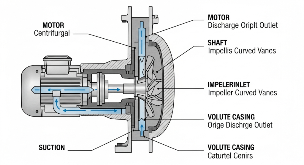
Understanding the internal components helps you diagnose problems, compare designs, and make sense of pump datasheets.
The Impeller
This is the core rotating element. It consists of curved vanes, usually enclosed between two discs in a closed impeller design mounted on the shaft. When it spins, energy transfers to the fluid. The impeller’s diameter, vane angle, and rotational speed directly control how much flow and pressure the system produces.
For fluids carrying suspended solids, open or semi-open impellers work better because they resist clogging (HAOSH Pump Engineering Reference, 2022).
The Volute Casing
The casing surrounds the impeller and collects high-velocity fluid leaving the vane tips. Its spiral geometry slows the fluid gradually, converting kinetic energy into pressure. Poor volute design is one of the fastest routes to low efficiency.
The Shaft
The shaft is what connects the impeller to the motor and transmits the torque that keeps everything spinning. Any slight misalignment here will cause vibration, premature bearing wear and seal failure.
Mechanical Seal
Sitting between the casing and the shaft exit point, the mechanical seal stops fluid from leaking along the shaft. Seal failure is one of the most common maintenance issues in industrial pump operations.
Bearings
Bearings support the shaft and allow smooth rotation with minimal friction. They handle both radial loads from the impeller weight and axial loads from pressure differences across the impeller. Worn bearings are a leading cause of vibration and abnormal noise.
Wear Rings
In order to reduce internal fluid recirculation, these are positioned between the stationary casing and the rotating impeller. Efficiency and flow decrease as they erode, and the decline is frequently slow enough to go unnoticed for months.
Suction and Discharge Nozzles
These are the inlet and outlet ports. Undersizing the suction nozzle creates high velocity at the eye, which drops local pressure and invites cavitation, one of the most damaging conditions a pump can experience (covered below).
Types of Centrifugal Pumps
Configuration depends entirely on what the system needs: how much flow, how much pressure, and what fluid is being moved.
Single Stage
One impeller. Moderate pressure, high flow. Perfect for water supply, irrigation, HVAC, and most general industrial applications. Simple and cost-effective to maintain.
Multistage
Multiple impellers in series inside a single housing. Each stage adds more pressure to the fluid. Used in boiler feedwater systems, high-rise building supply, and reverse osmosis plants where a single stage falls short.
Radial Flow vs. Axial Flow
In a radial flow design, fluid exits the impeller perpendicular to the shaft outward. Higher pressure, lower flow.
In an axial flow design, fluid moves parallel to the shaft like a ship’s propeller. Very high flow rates at low pressure, used in flood control and large cooling systems.
Mixed flow designs sit between the two.
Self-Priming
Standard designs cannot pull fluid upward from below their own inlet they need the casing pre-filled to create suction. Self-priming variants retain liquid after shutdown and use it to purge air automatically on the next start. No manual intervention needed.
Vertical vs. Horizontal
Horizontal layouts have the shaft running sideways, the most common industrial configuration, easy to access and service. Vertical layouts suit deep well or sump installations where floor space is tight.
Reading the Performance Curve
The pump performance curve is the most important document for system design and pump selection. It plots flow rate (Q) on the X-axis against head (H) pressure on the Y-axis.
Here is what the curve tells you:
- At zero flow, head is at its maximum (shutoff head).
- As flow increases, head decreases; the curve slopes downward.
- The Best Efficiency Point (BEP) is the flow rate where the pump delivers the most output for the least input. Operating too far from BEP wastes energy and accelerates internal wear (IPIECA, 2022).
Efficiency for well-designed units typically ranges from 60% to 80%, with large industrial models reaching up to 94% at optimal conditions (Pumps & Systems, 2023). In real-world installations, however, a Finnish research study found average efficiency below 40% largely because of oversized pump selection (C&B Equipment, 2024).
Running far from BEP is the most common and most avoidable mistake in pump system engineering.
Cavitation — The Problem That Sounds Like Gravel
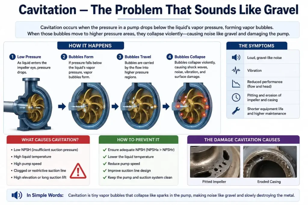
Cavitation is one of the most destructive phenomena in pump operation, and it sneaks up quietly.
Here is what happens. When pressure at the impeller eye drops below the vapor pressure of the fluid, liquid flashes into tiny vapor bubbles. These bubbles travel with the fluid into the high-pressure zone and collapse violently, producing micro shock waves that physically erode the impeller over time (Engineering Library, DOE Handbook).
Research published in PMC (National Institutes of Health) confirms when the pump head drops by 3%, the machine is already in a critical cavitation state.
Signs include:
- A crackling or gravel-like sound from the casing
- Falling flow rate and pressure
- Increased vibration
- Pitting visible on impeller surfaces after inspection
The root cause is almost always a poorly designed suction side, the wrong pipe diameter, too many fittings, or a suction lift that exceeds what the system can handle. Fix the inlet conditions first.
Why Priming Cannot Be Skipped
A standard pump cannot start dry. Fill the casing with air instead of liquid, and the impeller spins, but air is roughly 1,000 times less dense than water. The centrifugal force generated is 1,000 times weaker. No meaningful pressure builds. No flow happens.
This is why priming the suction side is mandatory before every startup.
Three common approaches:
- Flooded suction
Install the pump below the fluid source so gravity fills the casing naturally
- External priming
Manually fill the casing and suction pipe before starting
- Self-priming design
The pump retains liquid after shutdown and uses it to purge air on the next start
Skip this step, and you get dry running. Dry running destroys the mechanical seal and bearings within minutes.
Centrifugal Pumps vs. Positive Displacement Pumps
This comparison drives real engineering decisions constantly.
A positive displacement pump piston, diaphragm, or gear traps a fixed volume of fluid and physically forces it through the outlet each cycle. Flow stays constant regardless of pressure changes. These handle high-viscosity fluids and high-pressure applications well.
This design works best with low-viscosity fluids between 0.1 and 200 centipoise (Michael Smith Engineers, 2025). Above that range, efficiency falls sharply and a positive displacement type becomes the better fit.
Key practical differences:
| Factor | Centrifugal | Positive Displacement |
| Flow rate | Varies with pressure | Constant regardless of pressure |
| Best fluid | Low viscosity (water, chemicals) | High viscosity (oils, syrups) |
| Pressure capability | Moderate | High |
| Moving parts | Few | More |
| Maintenance | Lower | Higher |
In oil and gas, more than 90% of pumps are centrifugal due to capital efficiency and low maintenance requirements (IPIECA, 2022). Positive displacement types step in where precise metering or very high pressure is non-negotiable.
Where These Pumps Are Used
The applications span nearly every sector:
- Municipal water supply
Moving treated water through city distribution networks
- HVAC systems
Circulating chilled or heated water through buildings
- Power generation
Boiler feedwater and cooling water circulation
- Oil and gas
Pipeline transfer and processing
- Chemical plants
Handling acids, solvents, and process fluids
- Agriculture
Large-scale irrigation
- Pharmaceuticals
Sterile fluid transfer in controlled environments
The design simplicity, no valves, no pistons, and continuous flow make it the default choice wherever the fluid is thin and the volume is large.
Common Issues and How to Catch Them Early
Most field problems trace back to a handful of predictable causes.
Excessive vibration
Check shaft alignment first. Then bearings, then cavitation conditions. An impeller eroded unevenly also causes vibration that alignment checks won’t fix.
Seal leakage
Mechanical seals fail faster when the machine runs dry, operates far from BEP, or handles fluids outside its design range. Replace before leakage becomes a safety issue.
Falling flow and pressure
Worn wear rings, an eroded impeller, or air entering the suction line. Check for blocked suction strainers too.
Overheating
Dry running or prolonged operation against a closed discharge valve. Both overheat and damage the seal in minutes.
Routine maintenance covers bearing temperature checks, seal inspection, alignment verification, vibration monitoring, and confirming operation stays near BEP. A well-maintained pump runs for years with minimal intervention.
Frequently Asked Questions
Can a centrifugal pump run dry, and what happens if it does?
No, and it damages fast. Without liquid in the casing, the mechanical seal and bearings have nothing to cool or lubricate them. Seal faces overheat within minutes, bearings follow, and in severe cases the impeller seizes. If dry running is a real risk in your system, install a dry-run protection sensor to cut power automatically.
What is NPSH and why does it matter?
NPSH (Net Positive Suction Head) is the minimum pressure your system must deliver at the suction inlet to stop the fluid from vaporizing before it reaches the impeller. Every pump has an NPSHr (required) value from the manufacturer. Your system’s available NPSHa must always stay above it. When it doesn’t, vapor bubbles form, collapse violently inside the pump, and cavitation starts eating the impeller (Winston Engineering, 2025). Poor suction pipe geometry—long runs, sharp bends, and undersized diameter is the most common cause.
What is the difference between a single stage and a multistage centrifugal pump?
A single-stage unit has one impeller and produces moderate head fine for water supply, HVAC, and most general applications. A multistage unit stacks multiple impellers in series, each one adding more pressure, reaching head levels a single stage never could. The choice is simple: if your system needs high pressure, go multistage. If not, a single stage is cheaper and easier to maintain.
Why does a centrifugal pump lose efficiency with thick fluids?
The working principle depends on the impeller spinning fluid outward at high velocity. Thin fluids like water respond well. Thick fluids with higher viscosity create more friction between the fluid and the vanes, so the pump burns more power to move less fluid. Efficiency drops, sometimes sharply. This is why this design suits fluids up to around 200 centipoise. Above that, a positive displacement pump handles the job far better (Michael Smith Engineers, 2025).
Conclusion
The centrifugal pump operates in a clean, logical sequence: rotation in, fluid flow out. The impeller increases the velocity, the volute converts this velocity to pressure, and the system provides steady continuous flow without valves or pistons.
Understanding the working principle, the pump curve, cavitation behavior, priming requirements, and when this design beats a positive displacement alternative gives you the foundation for better engineering decisions whether you are selecting a new pump, diagnosing a field problem, or designing a system from scratch.
These machines are not complicated. They just need to be understood correctly.